
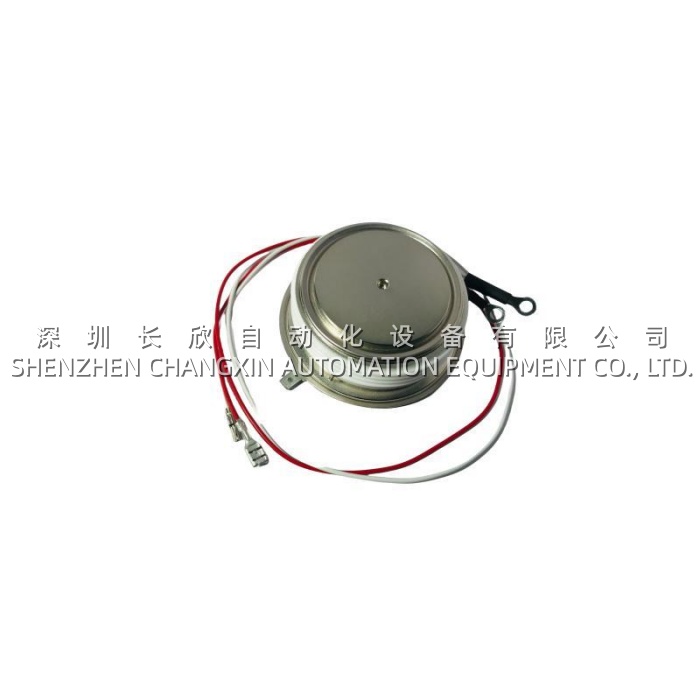
Technical Specifications
| Parameter Name | Parameter Value |
|---|---|
| Product Model | 5STP18H4200 |
| Manufacturer | ABB Switzerland Ltd, Semiconductors (5S / HiPak family) |
| Product Type | Phase-Control Thyristor, Press-Pack (Plate Type) |
| Repetitive Peak Forward/Reverse Blocking | VDRM / VRRM = 4200 V (f = 50 Hz, tp = 10 ms, Tvj = 5…125 °C) |
| Non-Repetitive Surge Blocking | VRSM = 4600 V (tp = 5 ms, single pulse) |
| Average On-State Current | IT(AV)M = 2075 A (half-sine, Tc = 70 °C) |
| RMS On-State Current | IT(RMS) = 3260 A |
| Peak Non-Repetitive Surge Current | ITSM = 32 × 10³ A (tp = 10 ms), 35 × 10³ A (tp = 8.3 ms), Tvj = 125 °C |
| Limiting Load Integral | I²t = 5.12 × 10⁶ A²s (10 ms), 5.0 × 10⁶ A²s (8.3 ms) |
| On-State Voltage | VT = 1.53 V @ IT = 2000 A, Tvj = 125 °C |
| Threshold Voltage | V(T0) = 0.96 V (IT = 1000–3000 A, Tvj = 125 °C) |
| Slope Resistance | rT = 0.285 mΩ |
| Holding Current | IH = 80 mA (25 °C), 60 mA (125 °C) |
| Latching Current | IL = 600 mA (25 °C), 200 mA (125 °C) |
| Critical di/dt (on-state) | 200 A/µs cont. @ Tvj = 125 °C; 1000 A/µs @ Vd ≤ 2810 V, IFG = 2 A, tr = 0.5 µs, f = 1 Hz |
| Critical dv/dt (commutating) | 1000 V/µs @ exp. to 0.67 × VDRM, Tvj = 125 °C |
| Circuit-Commutated Turn-Off Time | tq = 600 µs @ Tvj = 125 °C, ITRM = 2000 A, VR = 200 V, diT/dt = –1.5 A/µs |
| Leakage (Fwd/Rev) | IDRM / IRRM ≤ 300 mA @ VDRM/VRRM, Tvj = 125 °C |
| Mounting Force (Clamp) | FM = 45 kN (min) / 50 kN (nom) / 60 kN (max) |
| Weight | 0.9 kg |
| Package Dimensions | Ø101 mm plate, 26–26.6 mm thick (HF=50 kN), Ø63 mm active window |
| Creepage / Strike Distance | 36 mm / 15 mm |
| Gate Connection | Faston 6.3 × 0.8 mm; Aux. Cathode removable 0.5 mm² ETFE pigtail |
| Acceleration (unclamped/clamped) | 50 m/s² / 100 m/s² |
| Junction Temp Range | –40 … +125 °C (operating), –40 … +125 °C (storage) |
| Certification / Standard | IEC 60747-6, ABB internal HV device spec |
Main Features and Advantages
Free-Floating Silicon — ABB’s Flagship Die Stress Relief. The ABB 5STP18H4200 uses ABB’s patented free-floating silicon concept: the die sits on a molybdenum buffer between two copper headers but is not rigidly bonded at the edges, so during power cycling (cold → 125 °C → cold) the silicon does not accumulate shear from CTE mismatch (Cu ~17 ppm/K, Mo ~5 ppm/K, Si ~2.6 ppm/K). This directly extends power-cycling life — the failure mode that kills ordinary press-pack thyristors after 10⁵–10⁶ cycles shifts outward by an order of magnitude on the 5STP18H4200. For HVDC valves and arc-furnace rectifiers that see daily load swings, this is the differentiator.
Interdigitated Amplifying Gate for High di/dt. The gate structure on the ABB 5STP18H4200 is an interdigitated amplifying design — the incoming gate pulse fires a distributed pre-amplifier finger pattern under the anode, which then uniformly turns on the main cathode area instead of a point-initiated spread. Result: 200 A/µs continuous di/dt, 1000 A/µs under fast-transient commutating exposure (Vd ≤ 2810 V, which is ~0.67 × VDRM — i.e., the worst-case commutating overvoltage the device will see in a 4200 V bridge). For ACS6000 bridge arms where the PBA/PBT trigger fires fiber pulses into a local gate driver that sinks 2 A / 0.5 µs into the 5STP18H4200 gate, this di/dt headroom keeps turn-on spread uniform across the die and avoids local hot-spotting.
600 µs tq — Comfortable Margin for 50 Hz Line-Commutated Bridges. Circuit-commutated turn-off time tq = 600 µs @ 125 °C on the ABB 5STP18H4200 (ITRM = 2000 A, VR = 200 V, diT/dt = –1.5 A/µs, dvD/dt = 20 V/µs). In a 50 Hz / 60 Hz line-commutated bridge the available commutation dead-time per half-cycle is ~8–10 ms (50 Hz) or ~6–8 ms (60 Hz); 600 µs is ~6–10 % of that window, giving ample margin even when the AC system is stiff and the commutation angle compresses. This matters in HVDC LCC valves where a tq that’s too tight forces overdimensioning the series reactor or accepting higher risk during AC-fault recovery.
Press-Pack, Double-Side, No Bond Wires. The 5STP18H4200 is a pure compression device — no internal Al wirebonds, no solder on the current path (vacuum+H₂ protected chip-to-header solder is for thermal/electrical interface, not “wire” topology). Current flows axially through the copper headers, radial across the die, and out the opposite face. Both faces sit on heat-sink (usually water-cooled aluminum or CuCrZr in HVDC/ACS6000), so dissipation splits ~50/50. Compared to a module-case thyristor (plastic shell, wirebonds, single-side to heatsink through thermal pad), the ABB 5STP18H4200 has lower thermal resistance, no wirebond fatigue, and no plastic-outgassing in case of a flashover — important in valve-hall environments.
VT 1.53 V @ 2000 A = Low Conduction Loss. V(T0) = 0.96 V, rT = 0.285 mΩ → at 2000 A the ABB 5STP18H4200 drops 1.53 V, which is ~3 kW conduction loss per device. In a 6-pulse bridge at 2000 A that’s 6 × 3 kW = 18 kW bridge-wide — not trivial, but competitive in the 4200 V class. The low rT also means the on-state loss scales linearly rather than quadratic-excess, keeping the efficiency curve flat into overload.
Gate & Aux-Cathode Practicalities. The ABB 5STP18H4200 gate is a 6.3 × 0.8 mm Faston — standard ABB gate-driver PCB tangs (PBA/PBT family) plug straight on. The auxiliary cathode pigtail (0.5 mm² ETFE, red/white) is a removable spade; it gives the gate-driver a Kelvin reference so the gate-current voltage drop isn’t measured across the main cathode contact resistance (which varies with clamping force and thermal cycling). For commissioning techs this means the trigger waveform on the oscilloscope actually represents the die gate, not the contact artifact.