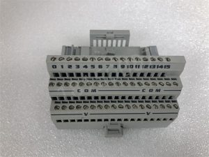
1794-TB3 AB
It receives and stores user programs and data input from the programmer according to the functions assigned by the PLC system program; Check the status of power supply, memory, I/O and alert timer, and diagnose syntax error in user program.

When the PLC is put into operation, it first receives the status and data of various input devices on site through scanning, and stores them in the I/O image area respectively. Then, it reads user programs one by one from the user program memory, interprets commands, and executes logical or arithmetic operations according to the instructions. The results are sent to the I/O image area or data register

After all user programs have been executed, the output states or data in the output registers of the I/O image area are finally transmitted to the corresponding output devices, and the cycle continues until it stops running.
In order to further improve the reliability of PLCs, in recent years, redundant systems with dual CPUs or voting systems with three CPUs have been adopted for large PLCs

In this way, even if a CPU fails, the entire system can still operate normally.
c. Memory
The memory that stores system software is called system program memory.
The storage for storing application software is called user program storage.
d. Input output interface circuit
1. The on-site input interface circuit consists of an optical coupling circuit and an input interface circuit of a microcomputer, serving as the input channel for the interface between the PLC and on-site control.

The on-site output interface circuit is integrated with output data registers, gate circuits, and interrupt request circuits, and functions as a PLC to output corresponding control signals to the execution components on site through the on-site output interface circuit.
e. Functional modules
Functional modules such as counting and positioning
f. Communication module
For example, Ethernet, RS485, Profibus-DP communication modules, etc