Application Scenarios
At a regional water reclamation facility on the U.S. West Coast, the influent pump station and chlorine dosing building were controlled by a Modicon Quantum PLC rack installed in 2008. The facility’s 230 V AC float switches, hand-off-auto selector stations, and motor starter auxiliary contacts were wired directly into four 140DAI74000 modules. When the plant underwent a reliability audit, inspectors discovered that the original relay-based input interface (used in a neighboring older station) had accumulated 37 wiring fault incidents over five years due to corroded interposing relay contacts. In contrast, the 140DAI74000-based station recorded zero interface failures over the same period. The module’s direct 230 V AC acceptance eliminated the relay layer entirely, and its 16 green channel LEDs enabled operators to visually verify float switch states without opening the panel door. When one 140DAI74000 eventually showed a flickering “Active” LED after 14 years of service, the maintenance team hot-replaced it during a scheduled 15-minute window—the 1-word addressing and factory-default configuration meant the new module was operational the moment it locked into the Quantum backplane, with no program download required.
Parameter
| Main Parameters | Value/Description |
|---|---|
| Product Model | 140DAI74000 |
| Manufacturer | Schneider Electric |
| Product Category | VAC Discrete Input Module |
| Compatible Platform | Modicon Quantum Automation System |
| Discrete Inputs | 16 channels (1 group of 16) |
| Addressing | 1 input word |
| Nominal Input Voltage | 230 V AC |
| Network Frequency | 47–63 Hz (50/60 Hz compatible) |
| Voltage State “1” Guaranteed | 165–264 V AC @ 57–63 Hz; 175–264 V AC @ 47–53 Hz |
| Voltage State “0” Guaranteed | 0–40 V AC |
| Input Current | ≤ 11.5 mA @ 57–63 Hz; ≤ 9.7 mA @ 47–53 Hz |
| Input Impedance | 26500 Ω capacitive @ 57–63 Hz; 31800 Ω @ 47–53 Hz |
| Response Time | 4.9–0.75 ms × line cycle (Off→On); 7.3–12.3 ms (On→Off) |
| Isolation | 1780 Vrms for 1 min (channel-to-channel & channel-to-bus) |
| Absolute Max Input | 264 V continuous; 300 V for 10 s; 400 V for 1 cycle |
| Bus Current Requirement | 180 mA |
| Max. Power Dissipation | ≤ 5.5 W |
| Local Signaling | 1 green “Active” LED; 1 red “Fault” LED; 16 green channel LEDs |
| Programming Software | Unity Pro, Concept, ProWORX 32 |
| Certifications | UL 508, CSA C22.2 No. 142, FM Class 1 Div 2, cUL, CE |
| Operating Temperature | 0°C to +60°C (32°F to 140°F) |
| Storage Temperature | -40°C to +85°C (-40°F to 185°F) |
| Weight | 0.35 kg (0.77 lb) |
| Terminal Block Required | Quantum 40-pin (e.g., 140XTS00200) |
| Lifecycle Status | Discontinued by OEM (Dec 31, 2021) |
Technical Principles and Innovative Values
Innovation Point 1: Direct High-Voltage AC Interface. The 140DAI74000 accepts 230 V AC directly on all 16 channels, eliminating the interposing relay layer that conventional 24 V DC input modules require for high-voltage field signals. This direct interface reduces wiring points by up to 50%, shrinks cabinet footprint, and removes the single most common failure mode in high-voltage digital acquisition—relay contact degradation. The capacitive input circuitry with 26500 Ω impedance draws ≤ 11.5 mA, ensuring minimal load on field devices while maintaining crisp, deterministic state detection.
Innovation Point 2: True 50/60 Hz Global Compatibility. Unlike frequency-locked input modules that only work on a single grid standard, the 140DAI74000 automatically adapts to both 47–53 Hz and 57–63 Hz network frequencies. The input impedance shifts from 31800 Ω (at 50 Hz) to 26500 Ω (at 60 Hz) to maintain consistent < 4.9 ms response times regardless of regional power standards. This makes the module a genuine global spare part—a single inventory SKU serves plants in North America, Europe, and Asia without recertification.
Innovation Point 3: 1780 Vrms Galvanic Isolation Barrier. The 140DAI74000 provides 1780 Vrms isolation for 1 minute between channels and between channels and the backplane bus. This barrier protects the Quantum processor, power supply, and adjacent low-voltage I/O modules from high-voltage surges, ground faults, or transient overvoltages originating in the field. Combined with the absolute maximum input rating of 264 V continuous (surviving 400 V for a single cycle), the module acts as a sacrificial shield for the entire PLC rack.
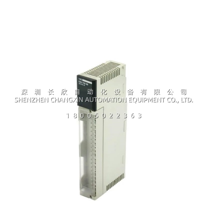
Innovation Point 4: Multi-Layer Front-Panel Diagnostics. The 140DAI74000 features 18 LEDs on its faceplate: 1 green “Active” confirms backplane bus communication, 1 red “Fault” flags external wiring anomalies, and 16 green LEDs mirror each individual channel’s real-time state. This three-tier diagnostic architecture lets technicians instantly distinguish between internal bus issues (Active LED) and field-side problems (Fault LED + channel LEDs)—cutting fault isolation time from hours to seconds.
Innovation Point 5: Deterministic 1-Word Address Efficiency. The 16 input channels of the 140DAI74000 occupy exactly 1 input word in the Quantum processor’s I/O map. This compact addressing scheme conserves precious memory space in large distributed systems where dozens of I/O modules populate a single rack, and simplifies ladder logic programming by presenting all 16 states as sequential bits within one word.