
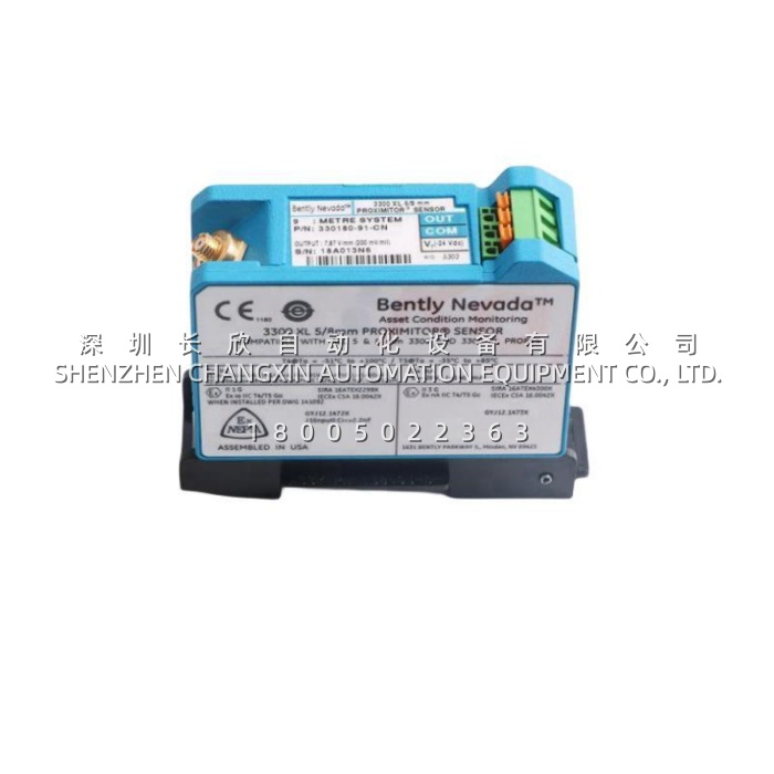
Application Scenarios
In centrifugal air compressor applications, the thrust bearing clearance between the shaft and bearing surface is often measured in fractions of a millimeter. A common challenge for OEMs and plant engineers is detecting excessive axial movement before it causes catastrophic metal-to-metal contact—yet the installation space around the bearing housing is frequently too tight for conventional thrust monitoring systems with external Proximitor drivers. The 991-06-50-01-01 addresses this by integrating the Proximitor sensor directly into the transmitter housing, eliminating the external driver that would otherwise consume valuable machine-mount space . Its 2-wire loop-powered design means the same pair of wires carries both power and signal, reducing wiring complexity and installation cost—a critical advantage when retrofitting axial position monitoring onto existing machinery where spare cable runs are limited.
Parameter
| Main Parameters | Value/Description |
|---|---|
| Product Model | 991-06-50-01-01 |
| Manufacturer | Bently Nevada |
| Product Category | 2-Wire Thrust Transmitter |
| Input Compatibility | 3300 NSv Proximity Probe + Extension Cable |
| Full-Scale Range | 0.6-0-0.6 mm (25-0-25 mils) total span |
| System Length | 5.0 meters (16.4 feet) |
| Mounting Option | 35 mm DIN-rail clips |
| Power Supply | +12 to +35 Vdc at transmitter terminal |
| Output Signal | 4-20 mAdc, 2-wire configuration |
| Loop Accuracy | ±1.5% over specified full-scale range |
| Maximum Loop Resistance | 1,000 Ω including cable at 35 Vdc |
| Current Limiting | 23 mA typical |
| Proximitor Output | 7.87 mV/μm (200 mV/mil) typical |
| Linear Range | 0.25 to 1.65 mm for Prox Out |
| Operating Temperature | -35°C to +85°C |
| Relative Humidity | 100% condensing, non-submerged |
| Weight | Approximately 0.43 kg (0.9 lb) |
Technical Principles and Innovative Values
Innovation Point 1: Integrated Proximitor Sensor Architecture. The 991-06-50-01-01 eliminates the need for a separate external Proximitor sensor by integrating this critical signal conditioning stage directly into the transmitter housing . This integration is particularly valuable in centrifugal air compressor installations where probe-to-shaft clearances are minimal. By removing the external driver, the 991-06-50-01-01 reduces component count, simplifies wiring, and eliminates a potential failure point in the monitoring chain.
Innovation Point 2: Not OK/Signal Defeat Circuit for False Alarm Prevention. The 991-06-50-01-01 incorporates a Not OK/Signal Defeat circuit that drives the loop output below 3.6 mA within 100 microseconds of detecting a probe or cable fault . This rapid response prevents the control system from interpreting a faulty probe signal as a valid high-thrust condition, which could trigger unnecessary alarms or protective shutdowns. The signal restores within 0.1 seconds after the fault clears, allowing the system to resume normal monitoring without manual intervention.
Innovation Point 3: Power-Up Inhibit for Transient Immunity. The 991-06-50-01-01 features a Power-Up Inhibit circuit that holds the output below 3.6 mA for 2-3 seconds after power application . This design eliminates signal errors that could otherwise occur due to line voltage transients during system startup, ensuring that the control system does not misinterpret startup artifacts as valid thrust data.
Innovation Point 4: Potted Construction for Harsh Environments. The 991-06-50-01-01 is encapsulated with a potted construction that protects internal electronics against 100% condensing humidity conditions . This environmental hardening makes the transmitter suitable for installation in outdoor compressor enclosures, cooling tower areas, and other locations where condensation is a persistent concern.