
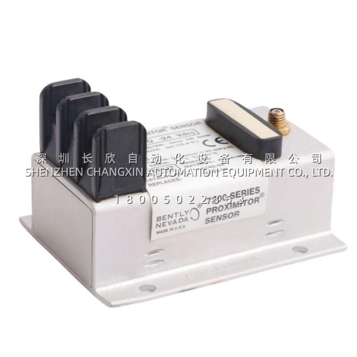
Description
The Bently Nevada 991-01-XX-01-05 is a two-wire, loop-powered thrust (axial shaft displacement) transmitter in the Bently Nevada 991 Thrust Transmitter family. It accepts the signal from one 3300 NSv non-contacting eddy-current proximity probe and its matching extension cable, conditions it into engineering units proportional to the axial position of a rotating shaft, and delivers it as a standard 4–20 mA signal to a PLC, DCS, or machinery control system. The 991-01-XX-01-05 occupies a specific and valuable niche: continuous thrust-position indication and alarming on smaller or non-critical rotating machines where a full API 670 protection rack is not justified, but catastrophic rotor-to-stator contact is still unacceptable.
Application Scenarios
A compressor OEM was packaging a two-stage centrifugal air compressor for a gas-processing facility. The customer’s control philosophy required a single 4–20 mA thrust-position signal per compressor that could drive an alarm and shutdown decision in the existing DCS — there was no budget, cabinet space, or maintenance expertise for a dedicated monitor rack, and the end user did not want another proprietary interface to support. The engineering team selected the 991-01-XX-01-05 because the Proximitor electronics live inside the transmitter body, eliminating the separate conditioner enclosure, rack slot, and interconnecting cable. They specified a 5.0 m system length for one skid and a 7.0 m length for a skid with a remote junction box, mounted the transmitters on 35 mm DIN rail inside the existing control enclosure, and delivered one calibrated thrust signal per compressor with no additional panel hardware.
In a second case, a refinery had a small high-speed pump set whose thrust-bearing clearance had tightened after a process upset. The original monitoring electronics were long out of production, and the pump was not classified as critical machinery — difficult to justify a full API 670 monitor upgrade. The maintenance team installed a 991-01-XX-01-05 at the pump, reusing the original 3300 NSv probe and extension cable. The 4–20 mA signal fed the existing DCS analog input, giving the planner a rising thrust-position trend and a clean low-current fault indication when the probe connection was disturbed during a cable pull. The pump stayed in service under monitored conditions until the scheduled turnaround, when the bearing was inspected and found to be near the end of its clearance tolerance.
Parameter
| Parameter | Value / Description |
|---|---|
| Product Model | 991-01-XX-01-05 |
| Manufacturer | Bently Nevada (a Baker Hughes business) |
| Product Type | Two-wire, loop-powered thrust / axial shaft displacement transmitter |
| Product Series | Bently Nevada 991 Thrust Transmitter |
| Ordering Code | 991-AA-BB-CC-DD (AA = full-scale option, BB = system length, CC = mounting, DD = agency approval) |
| Code AA | 01 = thrust / axial shaft displacement |
| Code BB (XX) | System length: 50 = 5.0 m / 16.4 ft; 70 = 7.0 m / 23.0 ft (probe + extension cable) |
| Code CC | 01 = 35 mm DIN rail clips |
| Code DD | 05 = agency approval package |
| Full-Scale Range | 0.6–0–0.6 mm (25–0–25 mils), bidirectional about zero (typical datasheet option) |
| Alternative Full-Scale | Standard datasheet options include 06 = 0.6–0–0.6 mm and 25 = 25–0–25 mils; confirm scaling against the original order code |
| Transducer Input | 1 non-contacting Bently Nevada 3300 NSv proximity probe with matching extension cable |
| Measurement Principle | Eddy-current, non-contacting |
| Output Signal | 4–20 mA DC, proportional to axial displacement; 2-wire configuration |
| Supply Voltage | +12 to +35 VDC at the transmitter terminals |
| Loop Accuracy | Within ±1.5 % of full-scale range, typical |
| Maximum Loop Resistance | 1,000 Ω including cable, at 35 VDC |
| Current Limiting | 23 mA typical |
| PROX OUT Linear Range | 0.25 to 1.65 mm (10 to 65 mils) |
| PROX OUT Scale Factor | 7.87 mV/µm (200 mV/mil), ±6.5 % typical including interchangeability error |
| PROX OUT Impedance | 10 kΩ output impedance, calibrated for a 10 MΩ load |
| Not OK Response | Output falls below 3.6 mA within 100 µs of a Not OK condition |
| Signal Recovery | Restored within 0.1 s after the Not OK condition clears |
| Zero / Span Adjustment | Non-interacting external potentiometers beneath the transmitter label |
| Test Input | Dedicated pin for loop verification with a variable DC voltage source |
| Minimum Target Size | 9.5 mm (0.375 in) diameter |
| Operating Temperature | −35 °C to +85 °C (transmitter) |
| Storage Temperature | −51 °C to +100 °C (transmitter) |
| Probe Operating Temperature | −52 °C to +177 °C |
| Humidity | 100 % condensing, non-submerged |
| Enclosure Construction | Fully potted; AISI 303/304 stainless steel case |
| Mounting | 35 mm DIN rail clips; bulkhead screws or DIN clips plus screws available on other mounting codes |
| Agency Approval | CSA Division 2, ATEX Zone 0, ATEX Zone 2, includes ABS maritime approval |
| Dimensions | 53.3 × 73.9 × 100.1 mm (H × W × D) |
| Weight | 0.43 kg (0.9 lbm) transmitter; approx. 0.82 kg total system |
| Country of Origin | USA |