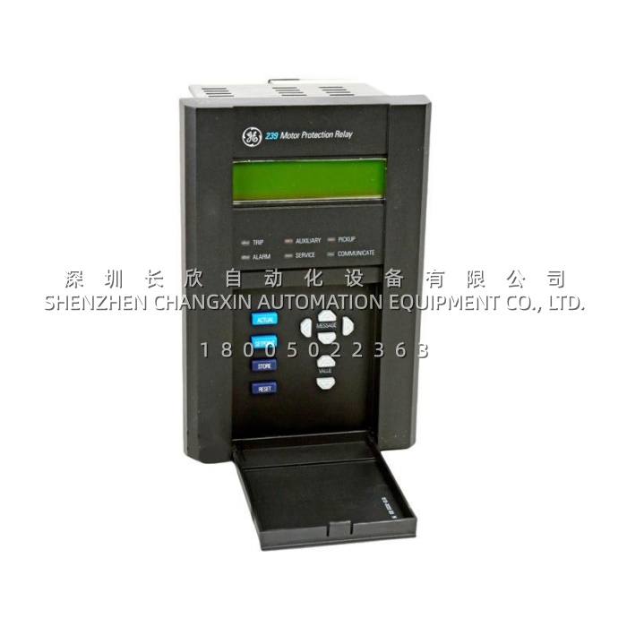
Technical Specifications
| Parameter Name | Parameter Value |
|---|---|
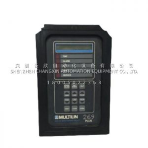
| Product Model | 269PLUS-100P-120 |
| Manufacturer | GE Multilin / GE Vernova Grid Solutions |
| Product Type | Microprocessor-Based Motor Management Relay |
| Series / Platform | Multilin 269 Plus (fixed, non-drawout version) |
| Control Power | 120 V AC nominal (approx. 90–150 V AC, 50/60 Hz); 125 V DC nominal |
| Power Consumption | 20 VA maximum |
| Phase CT Inputs | 3-phase CT, 1 A or 5 A secondary selectable |
| Ground CT Input | Zero-sequence CT, 50:0.025 A or 5 A secondary (configuration dependent) |
| RTD Inputs | Up to 10 inputs, 100 Ω platinum (3-wire); RTD 1–6 typically stator windings, remaining for bearing, ambient and load |
| Digital Inputs | 5 switch inputs (spare, differential contact, speed switch, external reset, emergency restart, access) |
| Output Relays | 4 Form C contacts — 1 latched main trip (86), 1 alarm, 2 programmable auxiliary |
| Analog Output | 1 isolated programmable output, 4–20 mA or 0–1 mA selectable |
| Communication | Isolated RS485, Modbus RTU; EnerVista 269 / 269PC setup software |
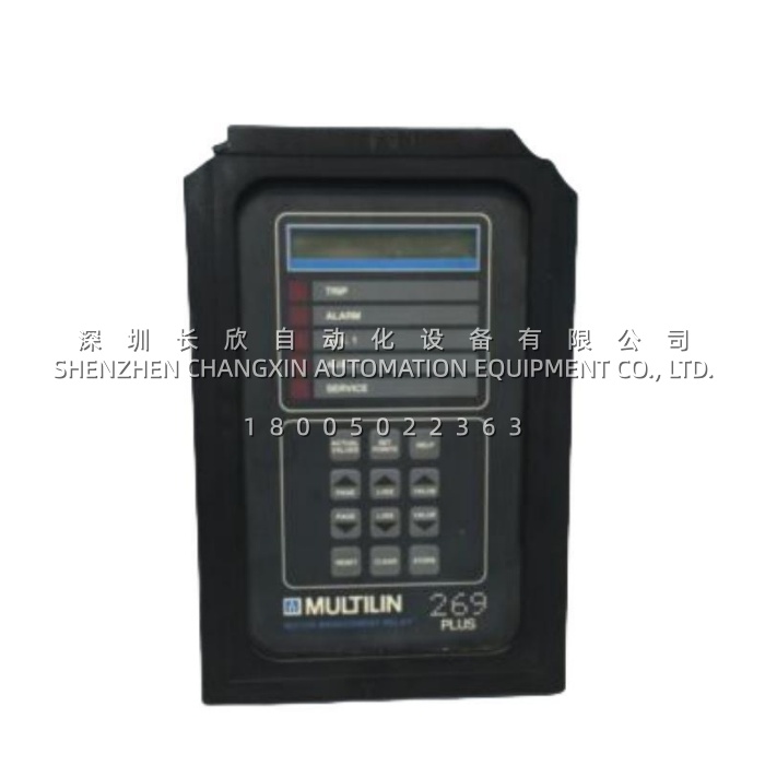
| Operator Interface | 48-character alphanumeric backlit LCD, keypad, 5 target LEDs |
| Protection Functions | Thermal overload (8 standard curves + FlexCurve), locked rotor, mechanical jam, short circuit, ground fault 50G/51G, unbalance 46, undercurrent 37, starts-per-hour 66, RTD overtemperature 49/38 |
| Measurement Accuracy | ±1% of primary CT amps for overload detection |
| Operating Temperature | −25 °C to +60 °C (some documentation cites −10 °C to +60 °C; confirm against the unit nameplate) |
| Storage Temperature | −40 °C to +85 °C |
| Humidity | 5–95% non-condensing |
| Enclosure Rating | IP53 / NEMA 12 with protective cover fitted |
| Dimensions (W × H × D) | Approx. 193 × 125 × 290 mm (7.6 × 4.9 × 11.4 in) |
| Weight | Approx. 2.8 kg (7.75 lb shipping weight) |
| Certifications | UL 508, UL 1053 (ground fault), CSA, CE; manufactured under ISO 9001 registered programme |
| Lifecycle Status | Discontinued by original manufacturer; available as new surplus or tested replacement |
Main Features and Advantages
Thermal modeling with RTD cross-check: The 269PLUS-100P-120 does not rely on current alone. It accumulates I²t to estimate thermal capacity used, then compares that estimate against actual stator RTD readings and tracks whichever value is higher. The MotorMatch function adds a second layer by learning real motor behaviour over time — acceleration time, cooldown time from run to stop, and the negative-sequence K factor — and adjusts the protection parameters to match the machine rather than the datasheet. This design approach is genuinely useful on older motors where the nameplate data no longer reflects actual condition, and it is the reason these relays are often kept in service rather than swapped for a generic overload block.
Customizable overload curves: Eight standard curves cover most applications, and where they do not fit, the FlexCurve function lets the engineer enter a user-defined curve point by point. For motors driving high-inertia loads — induced-draft fans, ball mills, long conveyors — acceleration time frequently collides with a standard curve, and being able to shape the curve avoids both nuisance tripping during start and under-protection during stall.
Ground fault and unbalance sensitivity: A dedicated zero-sequence CT input provides earth fault detection independent of the phase CTs, while negative-sequence measurement catches unbalanced supply and single phasing, which is one of the fastest ways to destroy a motor that is otherwise running below its rated load.
Emergency restart and restart inhibit: The 269PLUS-100P-120 supports an emergency restart input that can bypass the thermal lockout when process safety demands it, alongside a variable lock-out time and starts-per-hour limiting that prevent repeated starting on a hot machine. Both functions are configurable and can be tied to a key switch or a plant interlock.
Diagnostics that shorten fault finding: The relay stores time-stamped trip records, pre-trip values, cause of last trip, learned motor data, running hours and start counts. After an unexplained trip, reading the cause out of the display takes minutes instead of requiring a temporary data logger. Five target LEDs show which output operated while the LCD states why.
Integration without gateways: Modbus RTU over isolated RS485 connects the 269PLUS-100P-120 directly to most PLCs and DCS platforms, and the analog output carries thermal capacity or hottest RTD temperature to an analog input card where a digital link is not available.