
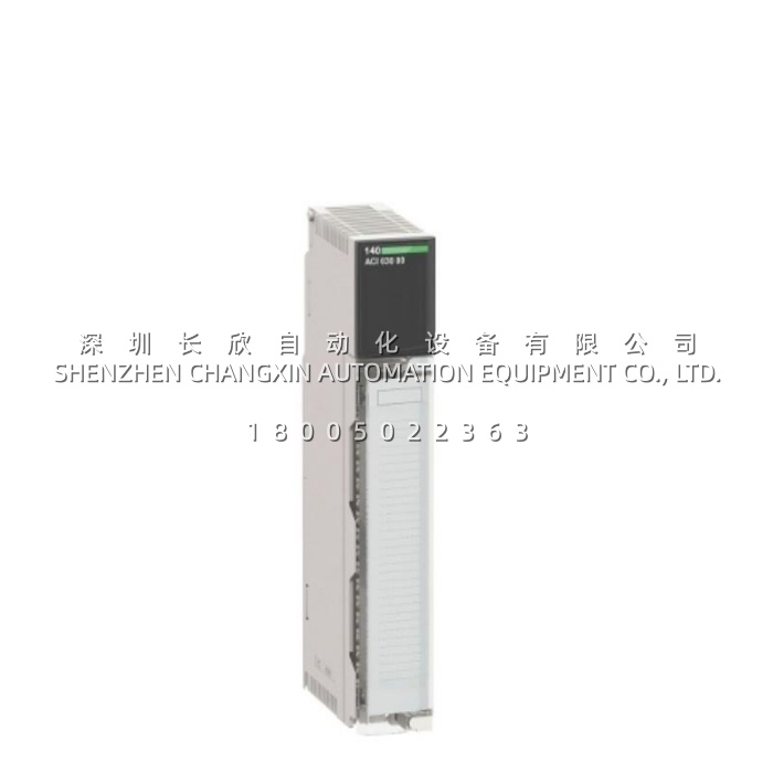
Application Scenarios
In a chemical processing plant, operators rely on analog signals from pressure transmitters, temperature sensors, and flow meters to maintain precise reaction conditions. A single faulty input channel can lead to inaccurate readings, causing product quality deviations or even safety hazards. The Schneider 140ACI03000 directly addresses this challenge by providing eight differential input channels with built-in broken-wire detection (for 4–20 mA loops) and undervoltage diagnostics (for 1–5 V signals). When a field wiring fault occurs, the module immediately flags the error via its LED indicators, allowing maintenance teams to pinpoint the issue without shutting down the entire system. In a real-world application, a water treatment facility using the 140ACI03000 to monitor pH, turbidity, and pump status achieved more stable process control and reduced unscheduled maintenance events, as the module’s rapid 5 ms update time and high common-mode rejection (>–72 dB at 60 Hz) ensured accurate readings even in electrically noisy environments.
Parameters
| Main Parameters | Value/Description |
|---|---|
| Product Model | 140ACI03000 |
| Manufacturer | Schneider Electric |
| Product Category | Analog Input Module |
| Number of Inputs | 8 differential channels |
| Input Resolution | 12 bits |
| Linear Measuring Range | 1–5 V and 4–20 mA |
| Absolute Max Input | 50 V DC / 25 mA |
| Input Impedance | >20 MΩ (voltage) / 250 Ω (current) |
| Update Time | 5 ms (all channels) |
| Absolute Accuracy Error | ±0.05% of full scale (typical) |
| Linearity Error | ±0.04% |
| Accuracy Drift | ±0.0025% of full scale/°C |
| Common Mode Rejection | >–72 dB at 60 Hz |
| Channel-to-Bus Isolation | 1000 V DC (3000 V DC for 60 s) |
| Channel-to-Channel Isolation | 30 V DC |
| Diagnostics | Broken wire (4–20 mA) / undervoltage (1–5 V) |
| Bus Current Requirement | 240 mA |
| Power Dissipation | 2 W |
| Addressing Requirement | 9 input words |
| Status Indicators | Active (green), Fault (red), 8 channel-on (green), 8 channel-fault (red) |
| Operating Temperature | 0°C to +60°C |
| Storage Temperature | –40°C to +85°C |
| Relative Humidity | 95% without condensation |
| Certifications | UL 508, CSA C22.2 No 142, FM Class 1 Division 2, cUL |
Technical Principles and Innovative Values
The Schneider 140ACI03000 combines precision analog measurement with intelligent diagnostics to deliver reliable performance in industrial automation environments.
- Innovation Point 1: High-Resolution Differential Input Architecture. The 140ACI03000 uses differential inputs with 12-bit resolution to accurately measure signals in the 1–5 V and 4–20 mA ranges. The differential configuration inherently rejects common-mode noise, while the built-in single-pole low-pass filter (3 dB at 15 Hz) attenuates high-frequency interference, ensuring stable readings in electrically noisy environments such as motor control centers and variable-frequency drive installations.
- Innovation Point 2: Comprehensive Built-in Diagnostics. A key advantage of the 140ACI03000 is its diagnostic intelligence. The module detects broken wires in 4–20 mA current loops and undervoltage conditions in 1–5 V voltage inputs, triggering a red “F” LED and per-channel fault indicators. This capability significantly reduces troubleshooting time and prevents invalid readings from propagating into the control logic, enhancing process safety and reliability.
- Innovation Point 3: Robust Galvanic Isolation for System Protection. The 140ACI03000 provides 1000 V DC isolation between channels and the bus (3000 V DC for 60 seconds) and 30 V DC channel-to-channel isolation. This isolation protects the Quantum PLC backplane and other modules from voltage surges and ground loops originating from field devices, extending system lifespan and reducing the risk of catastrophic failures.
- Innovation Point 4: HART Compatibility for Smart Instrument Integration. The 140ACI03000 is compatible with HART (Highway Addressable Remote Transducer) protocol, enabling the module to communicate with smart transmitters that overlay digital signals on the 4–20 mA analog loop. This allows users to access additional device information—such as calibration data and diagnostic status—without additional wiring, simplifying asset management and predictive maintenance.