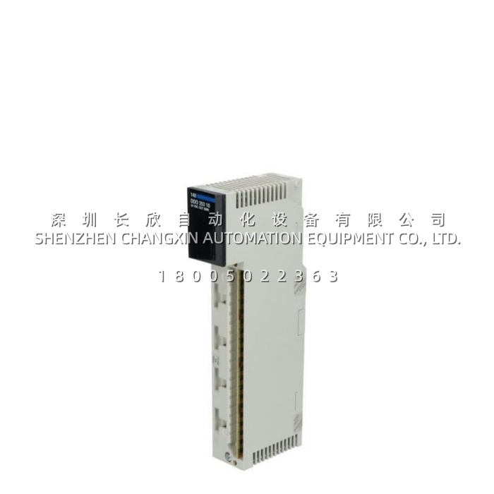
Application Scenarios
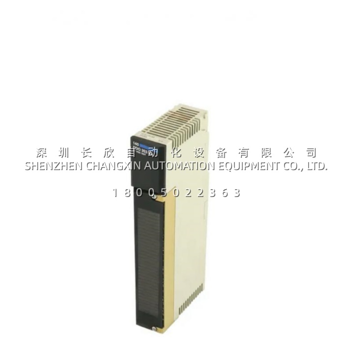
In a regional water‑treatment plant running a Modicon Quantum‑based SCADA system, the original output modules driving the chemical‑injection solenoid valves and dosing‑pump starters had become a chronic maintenance bottleneck: a single shorted solenoid would blow the module‑wide fuse and take down an entire 32‑point rack, forcing operators to manually jumper loads to keep the plant running. After replacing the legacy cards with the 140DDO35310, the maintenance team gained four independent groups of eight channels, each protected by its own 5 A internal fuse. When a contractor accidentally shorted a solenoid coil on Group 3, only that bank dropped out—Groups 1, 2, and 4 kept driving their valves, and the red Fault LED on the 140DDO35310 pinpointed the fault bank instantly. The plant’s control engineer estimated that the group‑level isolation and per‑bank fusing cut unplanned output‑related downtime by roughly 65 % over the following year. The ≤1 ms switching speed also tightened the dosing‑valve pulse‑width control, improving chemical‑feed accuracy and reducing annual reagent consumption by an estimated 7 %. The 140DDO35310 turned a fragile single‑point‑of‑failure design into a resilient, fault‑contained I/O architecture.
Parameter
| Main Parameters | Value/Description |
|---|---|
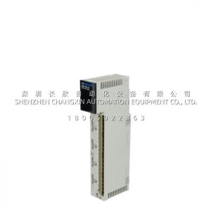
| Product Model | 140DDO35310 |
| Manufacturer | Schneider Electric |
| Product Series | Modicon Quantum 140 |
| Product Category | DC Discrete Output Module (Sink / Negative Logic) |
| Output Channels | 32 channels, arranged as 4 groups × 8 points |
| Output Voltage | 24 VDC nominal (19.2–30 VDC operating range) |
| Absolute Max Output | 50 VDC for 1 s decaying pulse |
| Max Load Current | 0.5 A per point; 4 A per group; 16 A per module total |
| Surge Current | ≤ 5 A for 1 ms |
| Voltage Drop | < 0.4 V at 0.5 A load |
| Off‑State Leakage | 0.4 mA at 30 VDC |
| Response Time | ≤ 1 ms (off→on) / ≤ 1 ms (on→off) |
| Max Tungsten Load | 12 W at 24 VDC |
| Channel‑to‑Bus Isolation | 1780 Vrms DC for 1 minute |
| Group‑to‑Group Isolation | 500 Vrms DC for 1 minute |
| Internal Protection | 5 A fuse per group; 3 A rating per point |
| Fault Indication | Loss of field power; blown fuse |
| Addressing | 2 output words |
| Backplane Bus Current | 330 mA @ 5 VDC |
| Power Dissipation | 2.0 W + (0.4 V × total load current) |
| Diagnostics LEDs | 1 green (bus active) + 1 red (fault) + 32 green (channel status) |
| Mounting | Standard single‑slot Quantum backplane (140XBP series) |
| Operating Temperature | 0 °C to +60 °C (32–140 °F) |
| Storage Temperature | ‑40 °C to +85 °C |
| Relative Humidity | ≤ 95 % RH, non‑condensing |
| Operating Altitude | ≤ 5000 m |
| EMC Immunity | ESD 4 kV contact / 8 kV air (IEC 801‑2); RF field 10 V/m (IEC 801‑3) |
| Certifications | UL 508, CSA C22.2 No 142, CE, FM Class 1 Div 2, RINA, GOST, C‑Tick, RMRS |
| Module Weight | 0.45 kg (0.99 lb) |
| Lifecycle Status | Commercial discontinuation 2022‑12‑31; service through 2030‑12‑31; new‑surplus stock available |
| Warranty | 12 months (new original) |
Technical Principles and Innovative Values
- Innovation Point 1 – Four‑Group Independent Isolation Architecture. The 140DDO35310 divides its 32 outputs into four physically segregated banks of eight channels, each with its own 5 A internal fuse and 500 Vrms inter‑group isolation. A short circuit or overload on one bank blows only that group’s fuse, leaving the other three banks fully operational. This fault‑containment design is a decisive advantage over single‑fuse 32‑point modules, where one bad solenoid can silence an entire rack.
- Innovation Point 2 – 1780 Vrms Channel‑to‑Bus Galvanic Barrier. Every output channel on the 140DDO35310 is isolated from the Quantum backplane at 1780 Vrms DC for one minute. This massive barrier protects the expensive controller backplane from field‑side inductive kickbacks, accidental 50 V surges, and ground‑fault transients—ensuring that a catastrophic field event will not propagate to the CPU or neighboring modules.
- Innovation Point 3 – Sub‑Millisecond Solid‑State Switching. Using high‑speed transistor sink circuitry, the 140DDO35310 executes state transitions in ≤ 1 ms both ways. This ultra‑low latency supports high‑frequency packaging lines, fast‑cycling sorting conveyors, and precise dosing‑valve pulse‑width control where mechanical relays or slower modules would introduce unacceptable jitter.
- Innovation Point 4 – Per‑Channel Visual Diagnostics. With 32 green channel LEDs, a green bus‑active LED, and a red fault LED, the 140DDO35310 gives maintenance staff a complete at‑a‑glance status window. A blown group fuse, loss of field power, or individual channel activation is visible without a laptop, a multimeter, or opening the cabinet—cutting average troubleshooting time from hours to minutes.
- Innovation Point 5 – Sink‑Logic Optimization for Common‑Positive Field Wiring. The 140DDO35310 is configured for negative‑logic (sink) operation, switching the load to ground. This perfectly matches common‑positive 24 VDC field wiring schemes found in most industrial plants, simplifying power distribution: a single shared +24 VDC bus feeds all loads, and the module provides the ground‑switching side. This reduces cabinet wiring complexity and terminal‑block count versus source‑type modules.