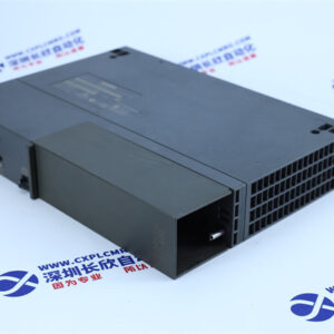

AI723F ABB
1. Measurement of voltage and current
Under normal circumstances, the two-phase current and DC voltage of the motor are measured simultaneously with the conduction position of the frequency converter power component.
2. Adaptive motor model
The measurement information from the motor is fed back to the motor model. The motor model is very complex, but only such a complex motor model can accurately calculate the motor data. Before running the DTC transmission device, it is first necessary to input some parameters of the motor, such as stator resistance, common impedance, saturation coefficient, etc. into the motor model. These parameters do not require manual input, but will be automatically input into the motor model after we input the correct motor nameplate data into the frequency converter and then perform motor identification operation. Of course, the identification of motor model parameters

t can also be carried out without rotating the motor rotor. That is to say, the identification operation of the motor can be carried out at zero speed
Complete, which makes DTC transmission more widely used. But if the control accuracy requirement is relatively high, the motor’s
Identify whether the operation needs to be completed at non zero speed.
When the static accuracy requirement is less than 0.5%, DTC transmission devices do not require encoders or tachometers. In fact
A static accuracy of 0.5% can meet the requirements of most industrial applications. No speed feedback required, it’s the DTC transmission area

An important characteristic that sets it apart from other AC drives. In fact, the motor model is that DTC transmission can perform well at low speeds
The key to good features.
The output control signal of the motor model directly reflects the actual torque and magnetic flux of the motor, while the
The shaft speed is also achieved in the motor model.
3. Torque comparator and magnetic flux comparator
The torque comparator and magnetic flux comparator jointly output pulse control information for the conduction of power components.

In a comparator, the actual values of torque and magnetic flux are compared with the given values every 25 microseconds, while the actual values of torque and magnetic flux
The state of the state is calculated through a double hysteresis control mode, which ensures the accuracy of the calculation and the stability of the controller.
After the signal is output from these two comparators, it goes to the next step – optimizing the pulse selector.