


4301-MBP-DFCM PROSOFT
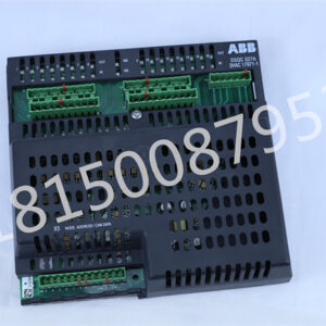
The ProLinx series Modbus Plus to DF1 master/slave communication module (5301-MBP-DFCM) establishes a strong connection between devices on the Modbus Plus network and DF1 slave devices. This module is an independent DIN rail mounted protocol gateway, providing a Modbus Plus configurable DB-9F port and a configurable serial port.

The Modbus Plus protocol driver exists in the dual Modbus Plus port (MBP). The driver can be configured as a host or slave on a single port basis to interface with other Modbus Plus devices. The Modbus port is fully configurable, providing great flexibility.
The DF1 (DFCM) protocol driver supports the host or slave implementation of the protocol on each DF1 port. All DF1 ports can be configured separately, providing great flexibility.

Therefore, if the input is a pulse signal, the width of the pulse signal must be greater than one scanning cycle to ensure that the input can be read in any case
During the execution phase of the user program, the programmable logic controller always scans the user program (ladder diagram) in a top-down order. When scanning each ladder diagram, always scan the control circuit composed of each contact on the left side of the ladder diagram first

and perform logical operations on the control circuit composed of the contacts in the order of left to right, top to bottom. Then, based on the results of the logical operations, refresh the corresponding bit status of the logical coil in the system RAM storage area; Or refresh the state of the corresponding bit of the output coil in the I/O image area; Or determine whether to execute the special functional instructions specified in the ladder diagram

That is, during the execution of the user program, only the state and data of the input points in the I/O image area will not change, while the state and data of other output points and software devices in the I/O image area or system RAM storage area may change. Moreover, the program execution results of the ladder diagram listed above will affect the ladder diagram below that uses these coils or data; On the contrary, for the ladder diagram below, the status or data of the refreshed logic coil can only be applied to the program above it in the next scanning cycl