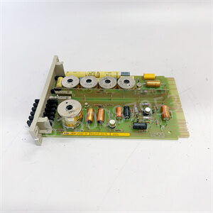
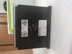
3200-1677 CONTREX
M-DRIVE is a cost-effective integrated controller and DC drive. The built-in thyristor driver can handle up to 2 horsepower permanent magnet DC motors and has adjustable current limits of 4 to 16 amperes. Digital controllers provide closed-loop speed regulation for applications that require the highest accuracy. Due to zero cumulative error, M-DRIVE can adapt to high demand electronic transmission applications commonly found in web processing and extrusion processes.

features:
No need for complex programming
Speed controller with built-in DC drive, suitable for motors up to 2 horsepower
A 10 millisecond control loop with zero cumulative error for precise speed ratio control
Adjustable PID gain and acceleration/deceleration ramp for improved stability control
The built-in LED display screen can be scaled to engineering units such as feet per minute
Optional:

Analog card: 1 input – zero to 10 V DC or 4-20 mA; 1 output – zero to+/-10VDC or 4-20mA; 12 bit resolution
Reverse setpoint programming; The set point is a divisor, not a multiplier. Typical applications include furnace time conveyors, per inch winding machines, or reverse stretching ratio feed rollers.

After the programmable logic controller is put into operation, its working process is generally divided into three stages, namely input sampling, user program execution, and output refresh. Completing the above three stages is called a scanning cycle. During the entire operation period, the CPU of the programmable logic controller repeatedly executes the above three stages at a certain scanning speed.

Input sampling
In the input sampling stage, the programmable logic controller sequentially reads in all input states and data in a scanning manner, and stores them in the corresponding units in the I/O image area. After the input sampling is completed, it enters the user program execution and output refresh phase. In these two stages, even if the input state and data change, the state and data of the corresponding units in the I/O image area will not change.