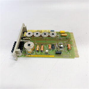
2213-75TSLKTB JDSU
Through interchangeable control modules, the axis can be converted to different networks or security functions
Dual port embedded switch supports device level ring (DLR) topology for EtherNet/IP application projects
Connect to enterprise, commercial, and industrial devices without the need for proprietary hardware or software

Safety functions include safety stop, zero speed monitoring, safety direction monitoring, and safety maximum acceleration monitoring
During continuous operation of machines or processes under restricted conditions, access to protected areas is more secure
Built in security features

The safety torque interruption is certified to comply with ISO 13849-1 PLe/SIL3. No external relays are required to meet the requirements of EN954-1 Class 3. Prevent the driver from restarting when the safety circuit trips.
The safety speed monitor combines the safety torque interruption function with an embedded safety relay using Rockwell Automation safety speed control core technology in an embedded hardware option of the driver. PLe/SIL3 certified
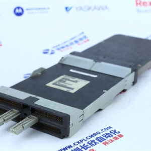
Rockwell AB driver with integrated Ethernet plugin

On the contrary, in the ladder diagram below, the status or data of the refreshed logic coil can only be applied to the program above it in the next scanning cycle.
If immediate I/O instructions are used during program execution, I/O points can be directly accessed. If I/O instructions are used, the value of the input process image register will not be updated. The program takes values directly from the I/O module, and the output process image register will be immediately updated, which is somewhat different from immediate input.

Output refresh stage
After scanning the user program, the PLC enters the output refresh stage. During this period, the CPU refreshes all output latch circuits according to the corresponding state and data in the I/O image area, and then drives the corresponding peripheral devices through the output circuit. At this point, it is the true output of the PLC
Although many names such as relays, timers, and counters are often used in the ladder diagram programs used by PLCs, these hardware are not physically present inside the PLC