
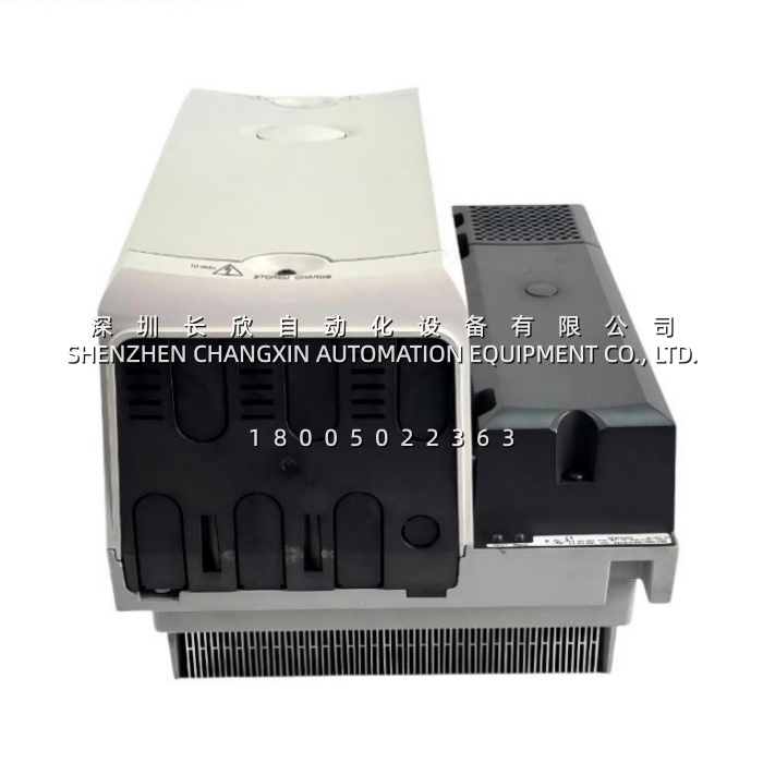
Application Scenarios
A paper machine or extrusion line often connects several inverter modules to one DC bus so that regenerative energy from a decelerating section can be used by another motoring section. In this arrangement, the input rectifier is not merely a passive converter; it must manage initial capacitor charging, suppress inrush current, supervise phase conditions, and deliver high DC-link current to the entire drive group. A standard uncontrolled diode bridge may be simpler, but it does not provide the same controlled charging capability.
The SPMC2402 addresses this application by converting 380–480 VAC three-phase power into DC bus voltage while ramping the precharge current rather than allowing the DC-link capacitance to draw an uncontrolled surge. Its dual rectifier stages provide two AC inputs and two DC outputs, supporting a high-current power architecture. In a common-bus system, this design helps reduce contactor welding, nuisance fuse operation, and capacitor stress during startup.
On a crane or hoist, the rectifier’s role becomes even more critical. The SPMC2402 supplies the DC link for inverter modules that manage acceleration, regeneration, braking, and holding functions. If the rectifier reports a fault, control wiring can disable the connected motoring drives, preventing unsafe operation when the front end is not available. This integration helps protect both the power modules and the mechanical system.
Parameter
| Main Parameters | Value/Description |
|---|---|
| Product Model | SPMC2402; “3” in the supplied name SPMC2402受控输入整流模块3 is not documented as an Emerson configuration digit and should be confirmed against the physical nameplate |
| Manufacturer | Emerson / Control Techniques; Unidrive SP family |
| Product Category | Controlled-input rectifier module |
| Product Type | Dual half-controlled thyristor rectifier |
| Input Voltage | 380–480 VAC, ±10% |
| Input Frequency | 50/60 Hz |
| Input Phases | Three-phase, 3-wire |
| Rectifier Configuration | Two stages; two three-phase AC inputs and two DC bus outputs |
| AC Line Current at 100% Normal Duty | 677 A |
| DC Link Current at 100% Normal Duty | 758 A |
| Typical Input Current | 2 × 308 A |
| Maximum Input Current | 2 × 312 A |
| Typical DC Output Current | 2 × 345 A |
| Maximum DC Bus Capacitance | 132 mF where supply short-circuit capacity is below 25 kA |
| DC Bus Capacitance with INL412 Reactor | 66 mF |
| DC Semiconductor Fuse Rating | 450 A, IEC aR type |
| AC Supply Fuse Rating | 400 A, IEC gG / UL J type |
| AC Input Cable | 2 × 120 mm², equivalent to 2 × 4/0 AWG |
| DC Output Cable | 2 × 120 mm², equivalent to 2 × 4/0 AWG |
| Soft-Start Function | Built into the SPMC module as standard |
| External Auxiliary Supply | 24 VDC, 3 A; requires a slow-blow 4 A fuse per pole |
| Control Wiring | 0.5 mm² typical |
| Status Indication | Two LEDs: Status 1 and Status 0 |
| Status Relay | 250 VAC / 6 A non-inductive; 4 A DC at 40 VDC; 400 mA DC at 250 VDC |
| Power Loss | Approximately 1737 W maximum |
| Cooling | Forced-air cooling with fan and surface-mounting accessories |
| Dimensions | 320 × 220 × 360 mm, or approximately 399 × 298 × 310 mm including mounting accessories; verify against the supplied configuration |
| Weight | Approximately 17.7–20 kg depending on assembly |
| Mounting | Surface or through-panel mounting using the supplied kit |