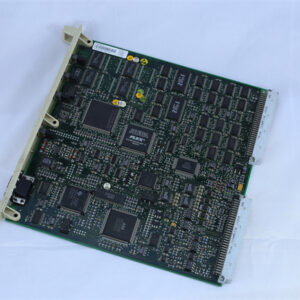
Application Scenarios: Inside a water-treatment plant’s main control panel, an SLC 5/04 processor mounted in a 1746-A7 chassis has outgrown its seven slots after a decade of incremental I/O additions — a new chemical-dosing skid needs six more discrete points, and the existing power budget cannot accommodate a wholesale platform migration. The retrofit path is a second 1746-A10 chassis mounted 18 inches to the right inside the same enclosure, linked to the original by a 1746-C9: the processor in chassis 1 now addresses modules in both racks as a single logical controller, the existing program and HMI integration remain untouched, and the expansion cable itself is the only new hardware component in the backplane path. The pain point the 1746-C9 solves is a classic SLC 500 constraint: the platform’s local I/O capacity is fixed by the chassis slot count, and the only supported way past that limit — short of migrating to a different control family — is a chassis-to-chassis ribbon link inside the same enclosure. That same pattern repeats across legacy OEM machine rebuilds, paper-machine and conveyor control retrofits, packaging-line panel expansions, and any SLC 500 installation where I/O growth has outpaced the original panel design but a control-platform migration is off the table.
Parameter
| Main Parameters | Value/Description |
|---|---|
| Product Model | 1746-C9 (Series A, “/A”) |
| Manufacturer | Allen-Bradley / Rockwell Automation |
| Product Category | SLC 500 Chassis Interconnect Cable (modular hardware style) |
| Cable Type | Flat ribbon, keyed 32-pin connectors (1746-RT32 termination hardware) |
| Cable Length | 914.4 mm (36 in / 3 ft) |
| Supported Chassis Spacing | 152.4 mm to 914.4 mm (6 to 36 in) horizontal; up to 92 cm (36 in) vertical A13 stacking |
| Compatible Chassis | 1746-A4, 1746-A7, 1746-A10, 1746-A13 (any combination) |
| Compatible Processors | SLC 5/01, 5/02, 5/03, 5/04, 5/05 (any SLC 500 modular-style processor) |
| Max Chassis per System | 3 interconnected chassis |
| Max Addressable Slots | 30 slots local (across all interconnected chassis) |
| Connection Orientation | Exits right side of first chassis, enters left side of second; keyed for proper orientation |
| Strain Relief | Rigid shrink wrap at both connector ends; flexible along cable body |
| Recommended Clearance | Minimum 4 inches (10.2 cm) between and around connected chassis |
| Recommended Horizontal Spacing | 15.3 to 20 cm (6 to 8 in) between chassis using 1746-C9 |
| Backplane Current Handling | 110 mA @ 5V DC / 85 mA @ 24V DC (surplus-supplier spec; passive cable) |
| Weight | 0.63 lbs (0.28 kg) |
| Operating Environment | Inside NEMA/IEC-rated enclosure, 0 °C to +60 °C ambient |
| Lifecycle Status | Discontinued by manufacturer; supplied as verified surplus or professionally rebuilt |