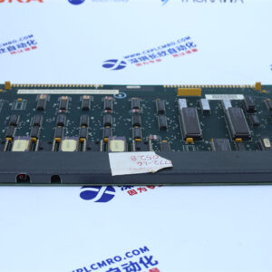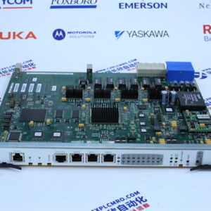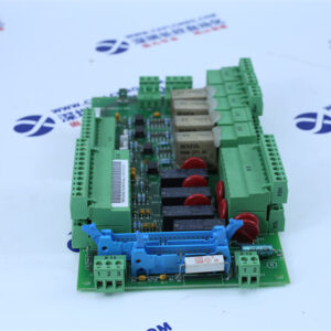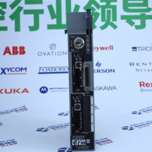
Technical Specifications
| Parameter Name | Parameter Value |
|---|---|
| Product Model | 1336-GM5-A |
| Manufacturer | Allen-Bradley (Rockwell Automation) |
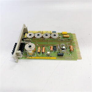
| Product Type | DeviceNet Communication Board / Embedded SCANport-to-DeviceNet Adapter |
| Product Family | 1336 Adjustable Frequency Drive Communication Options (Adapter 6, B Frame and up) |
| Compatible Drives | 1336 IMPACT, 1336 PLUS, 1336 PLUS II, 1336 FORCE, 1336 SPIDER |
| Network Protocol | DeviceNet (ODVA conformance-tested) |
| Device Role | DeviceNet slave / adapter |
| Supported Baud Rates | 125 kbps, 250 kbps, 500 kbps (DIP-switch selectable) |
| Default Baud Rate | 125 kbps |
| Node Address Range | 0–63 (DIP switches SW2-1 through SW2-6) |
| Default Node Address | 63 |
| Supply Voltage | 12–25 VDC (from DeviceNet network) |
| Current Consumption | 40 mA typical |
| Internal Interface | 14-pin SCANport connector (power + communication) |
| Network Interface | 5-pin removable Phoenix connector (open-style DeviceNet) |
| Communication Modes | Polled I/O, Change-of-State, Cyclic, Explicit Messaging |
| Datalinks | Up to 4 (A–D), enabled by DIP switches SW1-1 through SW1-4 |
| Default I/O | 16-bit logic command/status; 16-bit reference/feedback |
| Status Indicators | 2 dual-color LEDs: DeviceNet network status, SCANport status |
| Configuration | All settings via DIP switches; no software required |
| Mounting | Internal board mount on stand-off nylon headers, 4 Phillips screws |
| Enclosure Rating | Determined by host drive enclosure |
| Operating Temperature | 0 °C to 50 °C |
| Storage Temperature | −40 °C to 85 °C |
| Relative Humidity | 0% to 95% RH, non-condensing |
| ESD Withstand | 8 kV contact discharge |
| Certifications | DeviceNet conformance tested; CE |
| Lifecycle Status | Discontinued / obsolete (last-time-buy spare) |
| Reference Publication | 1203-UM010 |
Main Features and Advantages
Embedded form factor eliminates external hardware
The 1336-GM5-A mounts directly inside the drive on stand-off nylon headers and plugs into the internal 14-pin SCANport connector. There is no DIN rail to allocate, no mounting bracket to install, and no SCANport patch cable to route or maintain. In a crowded motor control center this saves real panel space, and it removes the external cable and its connectors—two of the most common points of failure in communication installations. For a plant standardizing on networked drives, the reduction in wiring, conduit, and terminal-block hardware across dozens of drives is substantial.
Configuration without software
Every essential setting on the 1336-GM5-A is a DIP switch. Node address, data rate, and datalink assignment can all be set on a bench before the board is installed in the drive. A spare can therefore be pre-configured to an exact node number and dropped in as a replacement in minutes, without requiring a laptop running RSNetWorx at the panel. This is a material advantage during an outage, when the priority is to restore the drive rather than to commission a network device.
Network diagnostics at a glance
The 1336-GM5-A carries two independent dual-color LEDs: one for DeviceNet network status and one for SCANport status. The separation is genuinely useful during commissioning and fault-finding. A network-side problem—duplicate node address, missing bus terminator, or bus-off condition—shows differently from a drive-side problem such as an unsupported datalink. This immediate visual distinction prevents the common mistake of blaming the network for a drive configuration issue, and vice versa.
Flexible I/O over a single drop
The 1336-GM5-A supports polled I/O for deterministic cyclic exchange, change-of-state messaging for event-driven, bandwidth-efficient updates, and explicit messaging for reading and writing drive parameters. Control commands, speed and torque references, acceleration and deceleration rates, status, output current, motor speed, DC bus voltage, and fault codes all travel across one DeviceNet drop. This removes the need for the extensive point-to-point wiring that would otherwise be required: separate wires for start, stop, forward, reverse, and fault reset, plus analog wiring for speed reference and feedback. The four configurable datalinks add two input and two output words each, allowing additional process values to be carried without consuming scanner I/O.
Bus-off node recovery without board removal
With DIP switches SW2-7 and SW2-8 set to On, the 1336-GM5-A supports changing the node address of a device that has gone bus-off using the appropriate software tool. This avoids pulling the board out of a drive merely to correct an address conflict—a small feature, but one that can save a significant amount of downtime when a scanner configuration has been changed remotely.