Application Scenarios
In a water-treatment plant running a 75 HP induced-draft fan on a 1336 PLUS II drive, a routine start-up ended with a hard “Overcurrent” fault that would not reset. The control board was healthy and the motor tested clear, so the fault had to be inside the power section. The 1336-BDB-SP29D was the prime suspect: it is the only board in that drive responsible for actually turning the six IGBTs on and off. After confirming bus voltage was zero, the maintenance team removed the failed board, inspected the IGBT bridge and DC-bus capacitors for secondary damage, and installed a tested replacement 1336-BDB-SP29D. The drive came back online without a parameter change, and the fan returned to service the same shift. That is the value of a field-replaceable gate-drive board — the rest of the drive stays intact, and a power-stage failure becomes a board swap rather than a full drive replacement.
Parameter
| Main Parameters | Value/Description |
|---|---|
| Product Model | 1336-BDB-SP29D |
| Alternate Part Number | 74101-169-53 (Rockwell internal cross-reference) |
| Manufacturer | Allen-Bradley / Rockwell Automation (USA) |
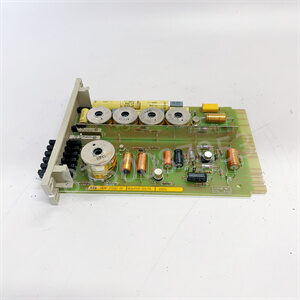
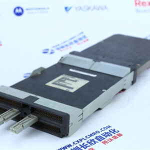
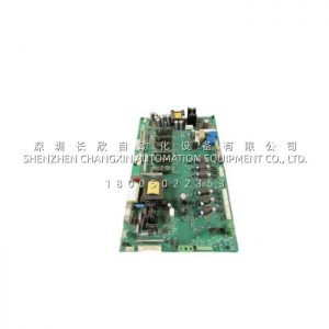
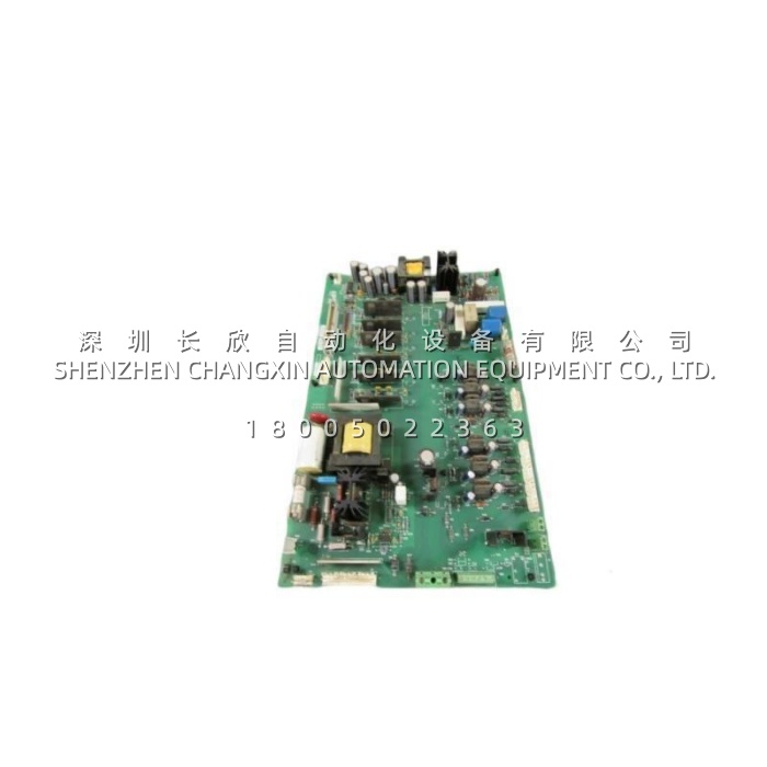
| Product Category | PCB gate drive / base drive board assembly |
| Compatible Drive Series | 1336 PLUS, PLUS II, FORCE, IMPACT, REGEN |
| Drive Voltage Class | 460 V AC, three-phase (input range commonly stated as 380–480 V AC) |
| Power Rating | Up to 75 HP (approx. 55 kW; some sources list 63 kW) |
| Frame Size | Frame D (some listings also state frames A–E depending on configuration) |
| Core Function | IGBT gate firing, feedback, and control interface for the inverter power stage |
| Gate Drive Channels | 6 independent channels (upper and lower IGBT of each of the three phases) |
| Input Signal | Low-voltage PWM gate-firing commands from the drive regulator / control board |
| Output | High-current, precisely timed gate drive pulses to six IGBT devices |
| Gate Drive Voltage | Typically ±15 V / –8 V class (drives IGBTs into deep saturation and hard off) |
| Isolation | Reinforced galvanic isolation between control electronics and high-voltage DC bus |
| Signal Interface | Ribbon / flat-cable headers and card-edge connectors for power and signal |
| Protection Functions | IGBT desaturation (DESAT) detection, short-circuit protection, overcurrent, overvoltage, surge suppression, undervoltage lockout (UVLO) |
| Board Substrate | FR4 epoxy glass laminate, multilayer construction |
| Termination | Screw-type terminals on associated assemblies |
| Dimensions | Approx. 39.3 × 24.4 × 4 cm (L × W × H) |
| Weight | Approx. 1.26 kg (some listings give 0.82 kg or 1.81 lb) |
| Shock Resistance | 15 G at 11 ms (operating); 30 G at 11 ms (non-operating) |
| Vibration Resistance | Up to 5 G |
| Operating Temperature | 0 °C to +40 °C or +50 °C depending on source |
| Storage Temperature | –40 °C to +85 °C |
| Relative Humidity | 5–95% RH, non-condensing |
| Protection Rating | IP20 (intended for cabinet-internal installation) |
| Compliance | UL, CE, RoHS as part of the 1336 drive system |
| Lifecycle Status | Discontinued / obsolete; supplied as new surplus or tested refurbished |
Note: Figures vary across third-party listings (e.g. dimensions 39.3 × 24.4 × 4 cm versus other sources, weight 0.82–1.26 kg, operating temperature 0–40 °C versus 0–50 °C). Verify against the board label, drive nameplate, and Rockwell documentation before ordering.
Technical Principles and Innovative Values
- Innovation Point 1 — Power-stage intelligence in one assembly. The 1336-BDB-SP29D combines gate drive, isolated auxiliary supplies, feedback, and protection on a single board. The drive needs no separate driver cards, which reduces parts count and the number of failure points in the inverter.
- Innovation Point 2 — Six channels, one per IGBT. Each phase leg has an upper and lower device; the board provides six independent drive channels so gate timing stays matched across the bridge. Matched timing is what keeps dead-time-induced distortion and shoot-through risk under control.
- Innovation Point 3 — Desaturation detection prevents destructive failures. While an IGBT conducts, the board monitors collector-emitter voltage. If an overcurrent or short-circuit pulls the device out of saturation, the 1336-BDB-SP29D sees the voltage rise and initiates a controlled soft shutdown before the power module is destroyed. Given that an IGBT stack costs many times more than the driver board, this function pays for itself the one time it is needed.
- Innovation Point 4 — Undervoltage lockout removes a failure mode. If the gate-drive supply sags, an IGBT can turn on only partially and dissipate destructive amounts of heat. The board holds the devices off until the supply is valid, eliminating a category of unexplained power-stage failures during brownouts and start-up.
- Innovation Point 5 — Reinforced isolation between control and power. Full galvanic isolation stops a high-voltage transient on the DC bus from propagating back into the control electronics. That barrier protects both equipment and personnel, and is why this board cannot be replaced by a generic signal-conditioning card.
- Innovation Point 6 — Revision-specific engineering. The SP29D suffix is not decoration. Gate-drive timing, layout, and signal paths differ between revisions, and a board that looks identical can misbehave in the power stack. Matching the installed revision preserves protection logic and stable gate-signal behaviour.