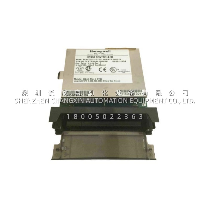
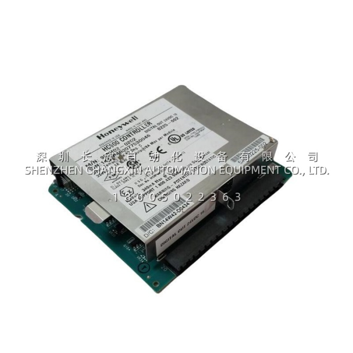
Application Scenarios:
A municipal water treatment facility running a legacy Honeywell installation hit a familiar wall: the original digital input cards were discontinued, and the third-party equivalents the team trialled introduced signal-compatibility problems with the plant’s existing terminal blocks and field wiring. The mix of devices made it worse — pump status came in as dry relay contacts, while valve position feedback came from 24 VDC proximity sensors, so any replacement had to handle both without a rewiring campaign.
Sourcing 900G02-0202 modules as direct replacements solved both problems at once. Because the card accepts the full 10–32 VDC range and works with the plant’s existing commons, the field side was untouched. The pluggable terminal blocks let electricians swap a card in under five minutes, and monitoring across four filter galleries was restored in a single shift.
The second pattern shows up in burner management. An HC900-controlled BMS needed additional digital inputs for flame scanner status and limit switch monitoring. The 900G02-0202 went into an available rack slot and, because the platform supports removal and insertion under power, the addition was commissioned without shutting down the burner. Per-channel LEDs gave immediate confirmation that every field device was landed correctly — which matters enormously in the narrow commissioning window before an annual plant startup.
Parameter:
| Main Parameters | Value/Description |
|---|---|
| Product Model | 900G02-0202 (assembly 51500209-004) |
| Manufacturer | Honeywell (ControlEdge 900 / HC900 platform) |
| Product Category | Digital input module, 16-channel, 24 VDC, sinking |
| Input Channels | 16, arranged as 2 groups of 8 with dedicated common terminals |
| Input Voltage Range | 10 VDC to 32 VDC; peak 32 VDC — wide enough to stay reliable when plant 24 V supply sags or runs high |
| Switching Thresholds | ON ≥ 9.5 VDC, OFF ≤ 3.5 VDC; min. ON current 1.0 mA, max. OFF current 0.7 mA — the gap between these figures is the noise margin |
| Input Impedance / Current | 2.6 kΩ nominal; 2.3 mA @ 12 VDC, 6.9 mA @ 24 VDC nominal |
| Response Time | 4 ms maximum, both OFF→ON and ON→OFF — adequate for high-speed discrete and totalising applications |
| Galvanic Isolation | 2 groups of 8 inputs, isolated up to 42.4 VDC; channel group to chassis |
| Backplane Power Loading | 5 V: 130 mA max; 24 V: 0 mA — all input energy comes from the field side |
| Status Indication | Green LED per channel (ON state); green blinking = module scanning; amber blinking = channel forced; red = module diagnostics |
| Hot Swap | Supported — Removal and Insertion Under Power (RIUP), auto-sensed and configured on insertion |
| Environmental | 0 °C to +60 °C operating; −40 °C to +85 °C storage; 5–95% RH non-condensing |
| Hazardous-Area Ratings | Class I, Division 2, Groups A, B, C, D T4; Class I, Zone 2, IIC T4; ATEX II 3 G Ex nA/ec IIC T4 Gc |
| Dimensions / Weight | Approx. 135 × 141 × 33 mm; approx. 175–230 g depending on build |
| Certifications | CE (EN61326-1, EN61010-1), UL Listed E201698, CSA, ATEX, RoHS 2 (except PSU) |