Technical Specifications
| Parameter Name | Parameter Value |
|---|---|
| Product Model | 369-HI-R-M-0-0 |
| Manufacturer | GE Multilin (GE Vernova Grid Solutions) |
| Product Type | Digital Motor Management Relay / Motor Protection Relay |
| Product Series | Multilin 369 Motor Management Relay |
| Order Code Breakdown | 369 base unit; HI = wide-range control power; R = 12 built-in RTD inputs; M = metering package; 0 = no fibre optic port; 0 = no optional protocol interfaces |
| Control Power Input | 50–300 V DC / 60–265 V AC, 50/60 Hz (nominal operating range commonly quoted as 110–250 V DC / 100–240 V AC) |
| Control Power Consumption | 20 VA nominal, 65 VA maximum |
| Phase Current Inputs | 3-phase CT, 1 A or 5 A secondary selectable, true RMS conversion, approx. 1.04 ms per sample |
| Ground Current Input | 1 A / 5 A CT or 50:0.025 sensitive zero-sequence CT; 20–100 Hz frequency range |
| RTD Inputs | 12 built-in three-wire inputs; supports 100 Ω platinum, 100 Ω nickel, 120 Ω nickel, 10 Ω copper; sensing current 3 mA |
| Digital Inputs | 6 optically isolated inputs |
| Output Relays | 4 Form C contacts (trip, alarm, and two programmable auxiliary outputs), configurable fail-safe |
| Analog Outputs | 4 isolated programmable channels, 0–1 mA / 0–20 mA / 4–20 mA selectable |
| Communication | 1 front RS232 port, 3 rear RS485 ports, Modbus RTU up to 19,200 bps |
| Overload Protection Curves | 15 standard curves plus user-programmable FlexCurve |
| Diagnostics | 512-event recorder, oscillography (3 records × 16 cycles), motor start data logger, motor health report, security audit trail |
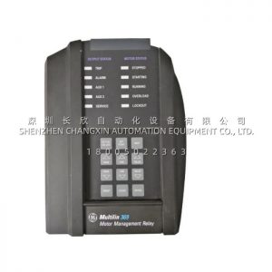
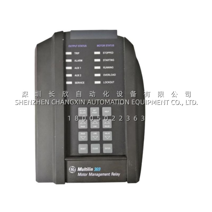
| Display and Interface | 40-character backlit LCD, keypad, motor status LEDs (stopped, starting, running, overloaded, locked out) |
| Operating Temperature | −40 °C to +60 °C |
| Storage Temperature | −40 °C to +80 °C |
| Humidity | Up to 95% non-condensing |
| Enclosure Protection | IP50X front panel, corrosion and flame retardant case |
| Dimensions (H × W × D) | Approx. 305 × 127 × 203 mm (12 × 5 × 8 in) |
| Weight | Approx. 4.5 kg |
| Fuse Rating | 3.15 A, 250 V, 5 × 20 mm |
| Certifications | UL, CSA, CE; manufactured under ISO 9001 registered programme |
| Lifecycle Status | Mature / discontinued by original manufacturer; available as new surplus or tested replacement |
Main Features and Advantages
Enhanced thermal model with RTD bias: The 369-HI-R-M-0-0 does not treat current and temperature as separate problems. It computes thermal capacity used from load current, then biases that calculation against actual stator RTD readings, tracking whichever value indicates higher stress. The dual time-constant design models heating and cooling separately, so the relay behaves differently during a long acceleration than during steady running. On motors with degraded cooling or high ambient temperature, this is the difference between a trip that happens before insulation damage and a trip that happens after it.
Learning capability rather than nameplate assumption: Motor parameters entered at commissioning are refined by measurement. The relay records acceleration time, cooling rate from run to stop, inrush current and negative-sequence contribution, then adapts. Where nameplate data has been lost or a motor has been rewound, this removes the guesswork from setting the overload curve.
Fifteen curves and FlexCurve: Standard applications are covered by fifteen built-in overload curves. Where a high-inertia load — an induced-draft fan, a ball mill, a long conveyor — produces an acceleration time that collides with every standard curve, FlexCurve lets the engineer define the profile point by point, avoiding both nuisance trips during start and under-protection during a stall.
Metering that replaces panel instruments: With the M option fitted, the 369-HI-R-M-0-0 measures voltage, current, real and reactive power, power factor, frequency and energy, and makes those values available both on the display and over Modbus. Four isolated analog outputs can carry current, thermal capacity, or hottest RTD temperature to a PLC analog input where a digital link is not available, which frequently removes several separate transducers from the panel.
Diagnostics that cut troubleshooting time: Five hundred and twelve stored events with one-millisecond time stamping, three oscillographic records of sixteen cycles each, and a start data logger mean that after a trip the sequence can be reconstructed from the relay. The motor health report summarises winding temperature trends, start counts and running hours, supporting planned intervention instead of reactive repair.
Practical integration: Three rear RS485 ports allow the 369-HI-R-M-0-0 to sit on a plant Modbus network while keeping a separate link for a local HMI or a second master, and the front RS232 port handles commissioning without disturbing the installed wiring.