Application Scenarios:
A coastal LNG terminal runs its seawater lift pumps on a duty/standby basis, eight starts per day per pump, with the MCC cubicles sitting 300 m from the intake in a salt-laden, 90 % RH atmosphere. The pain point is not dramatic failure — it is cumulative: repeated starts against a high-inertia load push the rotor and stator toward their thermal limits, and conventional bimetal overload relays simply cannot see it. They react to RMS current and guess at the rest.
That is exactly the gap the 269P-D/O-241-100P-HI fills. Its thermal replica tracks acceleration time, starts per hour, time between starts and cool-down rate simultaneously, and then corrects itself against real winding temperature from the 100 Ω platinum RTDs buried in the stator slots. When a pump is started too soon after a trip, the relay enforces the lock-out timer rather than letting an operator “try it once more”. On a drawout chassis, the whole unit can be swapped during a maintenance window with the CT shorting bars doing their job — no re-terminating, no outage extension.
The second scenario is quieter and more common: an ageing cement plant where the 269 Plus fleet is 20+ years old and the OEM has moved on. The 269P-D/O-241-100P-HI in that context is not a technology purchase, it is a risk purchase — keeping a working protection philosophy alive until the MCC is rebuilt.
Parameter:
| Main Parameters | Value / Description |
|---|---|
| Product Model | 269P-D/O-241-100P-HI |
| Manufacturer | GE Multilin (GE Grid Solutions), Markham, Ontario, Canada |
| Product Category | Microprocessor-based motor management / protection relay |
| Series | Multilin 269 Plus (269+) |
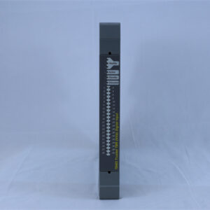
| Case Style | D/O = drawout chassis, removable without motor shutdown |
| Control Power | 90–300 V DC / 70–265 V AC, 50/60 Hz (“HI” high-voltage option) |
| Power Burden | 10 VA nominal, 20 VA max; ~100 ms ride-through at 120 V AC |
| Phase CT Input | 1 A or 5 A secondary, fixed by the “241” order code |
| Ground Fault CT | Core-balance 50:0.025 or x:5, per order code |
| RTD Inputs | Up to 10 total (6 stator typical + bearing/ambient); 100 Ω platinum; ±2 °C display accuracy |
| Output Relays | Trip (86, latched) + Alarm (74) + Aux 1 + Aux 2 |
| Contact Rating | 10 A at 250 V AC / 30 V DC resistive, AgCdO; not recommended below 0.1 A |
| Analog Output | Programmable 0–1 mA / 0–20 mA / 4–20 mA, ±1 % of full scale |
| Communication | RS485, Modbus RTU |
| Operator Interface | 2 × 24 character backlit alphanumeric display, 12-key keypad, 5 status LEDs |
| Dimensions (drawout) | 394 × 229 × 216 mm (15.50 × 9.00 × 8.50 in) overall |
| Weight | ≈ 2.9 kg relay only; drawout cradle and case add mass |
| Environment | −25 … +60 °C operating; 5–95 % RH non-condensing; 2,000 m altitude |
| Mounting | Panel cutout; 4 × 10-32 × 3/8 screws (standard) or 6 × #6-32 studs (drawout) |
| Approvals | UL recognized (file E83849), UL 508, CSA; built under an ISO 9001 program |
Note: the “241” block encodes the phase/ground CT pairing, the fail-safe code and the N.O./N.C. arrangement of the Alarm, Aux 1 and Aux 2 contacts. Drawout units are factory-configured — match the nameplate against the ordering table in manual 1601-0013 before swapping.
Technical Principles and Innovative Values:
Innovation Point 1: MotorMatch adaptive learning. Instead of forcing you to look up motor thermal constants, the 269P-D/O-241-100P-HI measures them. During commissioning and early starts it learns inrush current, negative-sequence K factor, cool-down rate, starting thermal capacity and acceleration time, then adapts its protection to the actual machine. On a motor with no usable datasheet — which is most motors over fifteen years old — this is the difference between a relay that protects and a relay that nuisance-trips.
Innovation Point 2: RTD-biased thermal model. Classic I²t replicas drift, because they assume a cooling model that stops being true the moment a fan shroud clogs or ambient rises 15 °C. The 269 Plus biases its thermal estimate with live stator RTD readings, so the model self-corrects against measured copper temperature. Practically, this lets you run closer to the thermal limit without eating winding life.
Innovation Point 3: FlexCurve beyond the eight standard curves. Eight standard overload curves cover most machines. When they don’t — a high-inertia fan with a long safe stall time, or a submersible pump with an unusual service factor — FlexCurve lets you enter a bespoke trip characteristic point by point rather than accepting the nearest compromise.
Innovation Point 4: A drawout mechanism that thinks about sequence. Two ten-finger connecting plugs, not one. Withdrawal requires removing the top plug first, which isolates the output relay contacts before control power is lost; insertion requires fitting the bottom plug first, restoring power before contacts re-enter the circuit. Combined with the CT shorting bars in the case, the 269P-D/O-241-100P-HI can be pulled and replaced live without opening a CT circuit — the single biggest safety hazard in relay work.
Innovation Point 5: Trip logic that survives a power failure. The trip relay is latched (ANSI 86) and the lock-out timer keeps running on loss of control power for up to one hour. A relay that forgets it tripped is a relay that permits a restart into a fault; this one does not forget.
Innovation Point 6: Fault forensics in non-volatile memory. Setpoints, learned parameters, pre-trip values, motor running hours, MWh, start counts and trip records persist through power loss. After a 2 a.m. trip, the data you need to decide “restart or investigate” is on the display, not lost.
Honest caveat: per the 269 Plus instruction manual, the drawout version does not meet CE compliance. If your project carries a CE declaration obligation, flag it before ordering rather than after the panel is drilled.
Application Cases and Industry Value:
Case 1 — Cooling water pump, petrochemical plant (690 V, ~450 kW). The plant was losing one pump motor roughly every eighteen months to stator winding failure, always traced back to a “start too soon after trip” event that the existing thermal relay permitted. Replacing the protection with a 269P-D/O-241-100P-HI wired to six embedded stator RTDs changed three things at once: starts-per-hour and time-between-starts limits were enforced in firmware; the lock-out timer became tamper-resistant; and bearing RTDs on a seventh and eighth input caught a lubrication problem two weeks before it would have become a seizure. The measurable outcome in this class of installation is typically the elimination of repeat-start burnouts plus one to two avoided unplanned outages per year, against a hardware cost that is a rounding error next to a rewind.
Case 2 — Kiln exhaust fan, cement works. Here the issue was process, not thermal: a broken damper linkage left the fan unloaded, and current dropped to 40 % of FLC with nothing to detect it. The undercurrent element (ANSI 37) on the 269P-D/O-241-100P-HI was configured to alarm at 55 % and trip at 45 % after a 10 s delay, wired to Aux 1 so the DCS got a distinct signal rather than a generic trip. Maintenance feedback was consistent on one point: the front-panel display and the stored pre-trip values cut diagnosis from “send someone to the MCC with a meter” to “read the last trip record over Modbus”.
The scenarios above are representative of how this relay class is applied; the numbers should be validated against your own motor nameplate, CT ratios and thermal limits before being used as a design basis.