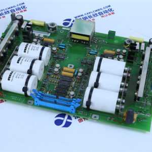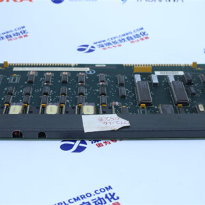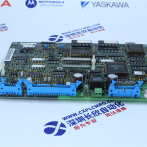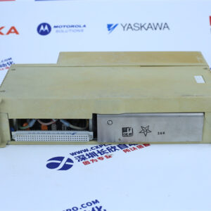
Technical Specifications
| Parameter | Value |
|---|---|
| Product Model | 211QS50003B |
| Manufacturer | Ansaldo (Ansaldo Sistemi Industriali S.p.A., Italy; drives business now Nidec ASI / Nidec Conversion) |
| Product Category | PLC control board / power trigger & supply board (“P board”) |
| Host Platform | Ansaldo SPDM fully digital DC converter, SILCOPAC D family |
| Supply Voltage (Trigger Section) | ±15 V DC |
| Supply Voltage (Control Section) | 24 V DC |
| Pulse Output Channels | 6 channels |
| Pulse Frequency | 5 – 10 kHz |
| Pulse Amplitude | 8 – 15 V DC |
| Pulse Width | 120° – 180° per cycle |
| Memory Configuration | 512 KB RAM + 1 MB Flash ROM (control board spec) |
| I/O Points | 16 inputs / 16 outputs (control board spec) |
| Communication Protocols | Modbus RTU, CANopen (control board spec) |
| Mounting | DIN rail or screw-mounted |
| Operating Temperature | 0 °C to +70 °C |
| Humidity | ≤ 90% non-condensing |
| Weight | approx. 0.2 kg (board only) / approx. 2.0 kg (shipping weight) |
| Protection Features | Phase-loss, overcurrent, opto-isolation between power and logic |
| Coating | Conformal coating for dust and moisture resistance |
| Indicators | On-board fault LEDs for rapid diagnostics |
| Country of Origin | Italy |
Main Features and Advantages
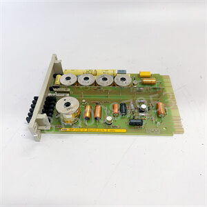
The Ansaldo 211QS50003B delivers a combination of triggering precision and local control intelligence that you rarely find in a single board. On the power side, the 211QS50003B produces six isolated gate pulses at 5–10 kHz with 120°–180° width and 8–15 V amplitude. This is exactly what a three-phase fully controlled thyristor bridge needs — six pulses, 60° apart, driving six thyristors in sequence to convert AC to DC with 0–100% output regulation. The high-frequency modulation ensures consistent firing even when the main supply is sagging or the load is swinging, which matters in drives rated from 35 A up to 4,000 A DC.
On the control side, the Ansaldo 211QS50003B handles the drive’s local sequence logic, interlock checking, and fieldbus communication. With 16 inputs and 16 outputs, 512 KB RAM, 1 MB Flash ROM, and Modbus RTU or CANopen support, the 211QS50003B can run the drive’s enable sequence, monitor external contactors, report status to a plant-wide PLC, and trigger alarms when things go out of range . This eliminates the need for a separate PLC card inside the converter cabinet and reduces both wiring and potential failure points.
The board’s industrial hardware design is straightforward and effective. The power and logic sections are optically isolated to prevent ground loops and EMI from corrupting the gate signals . The PCB uses thickened copper traces, conformal coating, and gold-plated connectors for long-term reliability in dirty, hot, and electrically noisy cabinets . On-board fault LEDs give maintenance teams instant visual feedback — one glance at the Ansaldo 211QS50003B tells you whether the supply rails are stable, the pulses are present, or the board has tripped on an internal fault. Overcurrent, phase-loss and over-temperature protection circuits are built into the board’s monitoring logic, so the 211QS50003B can shut down the gate pulses before a downstream fault escalates into a blown thyristor or a cabinet fire .